Model | HV Laser power Series |
---|---|
Input Voltage | AC220V±10% (Need AC110V products, ordering need indicate) |
AC frequency | 47 - 440HZ |
Cold-state Surge Current | ≤60A(AC220V input) |
Leakage current | ≤0.7mA(AC220V input) ≤0.4mA(AC110V input) |
Maximum output voltage | 50KV DC |
Maximum output current | 40mA(depending on the laser tubes of different manufacturers) |
Efficiency | ≥90%( Full load) |
Response speed | ≤ 1ms |
Control Interface | TTL multilevel switching control |
Input--output insulation | AC 1500V 1 minutes ≤10 mA |
Input--shell insulation | AC 1500V 1 minutes ≤10 mA |
Output--shell insulation | Connection |
Insulation Resistance | ≥50MΩ(DC500V) |
Working temperature | -10 to +50 deg |
Relative Humidity | Maximum 85% RH (non-condensing) |
Cooling methods | Forced air cooling (fan cooling) |
These power supplies are used in Laser cutting, engraving, marking applications.
The YAG series laser power supplies are made for CW lamp-pumped Nd:YAG lasers. The main circuit of the power supply is based on power electronic module IGBT, adopts PWM technique to yield conversion efficiency more than 90%, and outputs constant current with high accuracy and low current ripple. Ignition circuits which produce a high voltage pulse consists of three steps: series high voltage unit for igniting the lamp, LC unit to relay the power, and low –voltage-constant-current to continue the lamp current. Automatic igniting is achieved with igniting-detecting circuit. The successful ratio of one-time ignition is more than 99%. The high voltage rises smoothly, and its magnitude can be adjusted to meet the dispersible characteristics of the krypton lamps, and to reduce the spattering of the electrode material at the same time, and further to reduce the damage to the krypton lamp caused by high voltage triggering.
The soft-charging circuit and soft-starting circuit are provided to avoid the voltage spiking and in-rush current in the event of starting. Display shows the set current and operation current at different time. The function of “work/sleep” is designed to output normal current at working and low holding current at the time of stand by, so as to increase the efficiency of the power supply, lighten the heat exchanger system, and prolong the lifetime of the lamp as well. Conveniently turns switch to Run/Stop status, adjust output current, and show the working status through the inner/outer control selection.
Excellent design makes the power supply maintained easily and perfect design of circuit protects the device from over voltage, over current and over heat.
Parameters | Values |
---|---|
Max output current | 25 |
Max output voltage | 200V |
Current ripple | ≦0.4% |
Control accuracy | 0.40% |
Simmer current | 7A |
Switching frequency | 20KHZ |
Allowed input voltage tolerance | ±15% |
Environment temperature | 0~50℃ |
Environment humility | ≦90% |
Input electricity | 380V, 6KVA |
These driver modules are a compact, high power pulsed current source designed to drive diode lasers, bars and arrays in pulsed, QCW or CW modes. It delivers output current variable from 1A to 125A, pulse widths variable from 1us to DC and pulse repetition frequencies variable from single-shot to 500KHz at duty cycles up to 100%.
These modules feature a user-adjustable variable rise time control. This innovative feature allows the user to adjust the rise time within a range of 2.5μs by means of a PCB-mounted potentiometer, to optimize the driver's rise time for the user's application. These are based on a hysteretic, average current, switch-mode regulator. This type of regulator is a variable frequency, variable pulse width design which maintains current in an energy storage inductor between a minimum and maximum level. This architecture provides a high performance driver in a small form factor, with high operating efficiency and low stored energy.
At 125A output current, the stored energy in the driver is approximately 7 Joules, dramatically lower than the stored energy in comparable linear current sources.
PULSE OUTPUT CURRENT | Values |
---|---|
Amplitude Range | 0.0001A to 125A |
Means Of Adjustment | Trimpot Mounted on PCB or External Analog Voltage Program |
Output Polarity | Positive |
Pulse Rise Time | Variable From <30nS to >2.5uS,(10% to 90%) User Adjustable |
Pulse Width | <100nS to DC |
Pulse Recurrence Frequency | Single Shot to 500kHz |
Maximum Duty Cycle | 100% |
Output Pulse Ripple/Droop | ~2A (<2% at 125A) |
Jitter | <3nS First Sigma |
Efficiency | >75% at 50% Duty Cycle 125A |
Output Connector | >High Current DSUB PCB Mounted |
DIODE FORWARD VOLTAGE | |
Amplitude | 20V Maximum |
GATE INPUT | |
Type | Positive Edge Trigger |
Gate Input | +5V CMOS |
CONTROL FUNCTIONS | |
Output Enable/Disable | TTL Input High = Enabled |
GENERAL | |
Input Power | +24VDC Unregulated (different voltage options available) |
Operating Temperature | 0ºC to 40ºC |
Cooling | Air Cooled |
These modules are designed to drive diode lasers, bars and arrays in pulsed, QCW or CW modes.
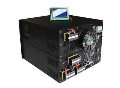
These power supply generate current pulses (QCW mode) that can be set between 0 and 500 A, with adjustable pulse width from 20 µs to 3 ms, and an average power (peak power by duty cycle) of up to 1000 W. It is packaged in a self-cooled 3U rack, with a user-friendly front-panel touch-screen interface. This power supply is suited for powering High Power Laser Diodes in a very versatile way, offering several control options, such as internal or external trigger, pulse duration, single shot to any repetition frequency rate.
It also displays applied pulse characteristics: current, voltage and pulse duration. All commands, controls data and pulse measurements are also available through the digital communication bus (I2C, SPI, CAN) or Ethernet (as an option).
The power supply also features all necessary protections to ensure the safety of the laser diodes (and driver) against overcurrent, overvoltage, short and open circuits, and over temperature. All the parameters are user-adjustable.
A second independent channel is offered as an option and can be used either independently or in parallel with the 2nd channel for higher operational current (with the ability to drive diodes up to 1000 A under 100 V). The power supply generates current pulses (QCW mode) adjustable between 0 and 500 A, with pulse durations from 20 µs to 3 ms, at an average power up to 1000 W. The driver is packaged in a self-cooled 3U rack, which includes the AC/DC convertor and a user-friendly front-panel, touch-screen interface.
Power Supply | Values |
---|---|
Input Voltage | 85 VAC to 265 VAC / 45-65 Hz (Universal AC) |
Load Output | |
Diode IR voltage | 10 - 100 V floating |
Output peak current | 0 to 500 A |
Output peak power | 50 kW |
Output average power | 1000 W |
Pulse duration | 20 to 3000 µs, limited to 150 J pulse energy |
Current rise time (10 % - 90 %) | 10 µs typical (depending on cabling), without overshoot |
Current rise time (90 % - 10 %) | 10 µs typical (depending on cabling) |
Pulse repetition frequency | 0 to 500 Hz (limited by pulse duration and average power) |
Pulse to pulse stability | < 0.10 % |
Jitter | < 100 ns |
Input - Output insulation | 2000 VAC |
Output - Chassis insulation | 500 VAC |
Interface | |
Communication protocol | CAN, I2C, SPI or Ethernet |
Synchronization | Internal or external |
Pulse mode | Single or repetition |
Control mode | Remote or local |
Internal protections | |
Permanent short circuit | |
Over load protection | |
Display | |
Front LEDs | Ready (green), Laser on (orange), Error (red) |
Control elements | |
Keys | Switch button On/Off |
Emergency stop key | Instantaneously shut down all power circuits |